H Bridge Mosfet Driver
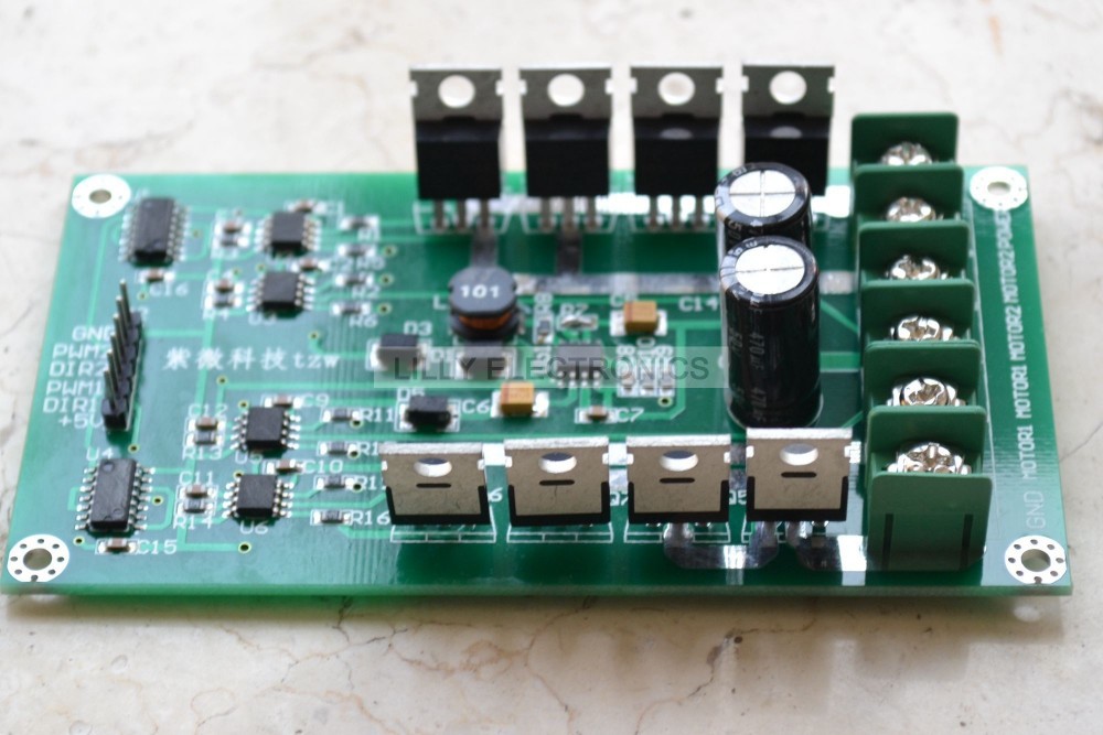
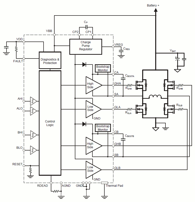
For example if using an L6203 DMOS Full H-Bridge Driver that has a max RMS current of 4A, do you then need at least 4A doides for the catch diodes or is there some other way to calculate the required value? I have built the following H-bridge driver circuit (The red resistors R9 and R10 were not included). However during testing I have found that I am constantly blowing the high side P-Channel MOSFETS which has lead me to believe the driver circuitry has problems. You might as well get away with a 4 N channel mosfet H bridge, which is likely to perform better than a 2N + 2P one because N channel mosfets are usually better at switching than the P mosfets. You will either need a mosfet driver or use a higher voltage for switching the high side mosfets.
H Bridge Mosfet Driver
Also study the links below on transistor switching circuits before you attempt to build any of these devices. Permanent magnet DC motors have been around for many years and come in a variety of sizes and voltages. Their direction of rotation is dependant upon the polarity of the applied voltage. Reverse the voltage, the direction of rotation reverses.
One of the most common solid-state controls is known as the H-bridge. In figure 1 we have a very basic H-bridge using two spring-loaded, single-pole, double-throw switches. The normally closed (NC) contacts are grounded and normally open (NO) contacts are connected to +12 volts. A DC motor is connected between the two commons. In its normal state, both motor connections are grounded through the switches.
Both switches are spring loaded. If we press SW1 the NC contact opens and the NO closes supplying +12 volts to one side of the motor while the other side is still grounded through SW2. The motor will spin at full speed say counter-clockwise.
Release Sw1 and press SW2 and +12 volts is supplied to the '+' side of the motor while the negative side is grounded through SW1. The direction now is clockwise. Press both switches and both sides of the motor will be at +12 volts and won't run.

• • • • • • • • Spec sheets to transistors used here. • • Now we will look at practical MOSFET H-bridge circuits. Check the above links if not familiar with transistor switching circuits. Figure 12 Now I will address other issues.
 We're all just doing our own thing)'. There's no bad blood, nobody hates each other, nobody's mad at each other. We're all sort of on our own right now, doing our own thing. It's realistically, I don't see anything happening with Atoms Family again.
I will be normal for the p-channel MOSFET to get hotter than the n-channel. This is due to higher DS-on resistance of the p-channel. Rb serves to discharges the gate-source circuit to turn off Q2.
In the past I used a 10K resistor, it can be dropped to 1000 ohms. This can result in faster turn off. The 1N914 diode across Rb suppresses any gate-source discharge noise with Rb. Finally we can use a NPN transistor instead of an opto-couple. 2014 • YouTube • • • YouTube • • • • YouTube • • • • YouTube • YouTube • • • YouTube • • • YouTube • • • • • • • • • • • • • • • • • • • • Added Nov. 16, 2014 • • • • • • • • • • • • • • • • •.
H-Bridge THE H-BRIDGE The H-Bridge is designed to drive a motor clockwise and anticlockwise. To reverse a motor, the supply must be reversed and this is what the H-Bridge does. An H-Bridge can be made with SWITCHES, RELAYS, TRANSISTORS or MOSFETS. Note: Some circuits are just demonstration circuits and need 'damper diodes' (protection diodes) to reduce spikes.
Make sure that you warm-up on your product at a slow pace. • TR O UB L E SH O OTI NG COMMON PRODUCT QUESTIONS ARE THE SOUNDS MY TREADMILL MAKES NORMAL?  All treadmills make a certain type of thumping noise due to the belt riding over the rollers, especially new treadmills.
H-Bridge with switches: Do not make circuit 'A.' It can easily create a SHORT-CIRCUIT. It is only a demonstration circuit.

Switch A and D will make the motor rotate clockwise. Switch B and C will make the motor rotate anti-clockwise. Switch A and B will create a BRAKE. Do not close switch A and C at the same time. Do not close switch B and D at the same time. An improved design is shown in Circuit C.
It does not create any short-circuit: H-Bridge with a relay: The top diagram shows the underside of a double-pole double-throw relay The motor is active at all times. Push the button to reverse the direction of rotation. H-Bridge with 2 relays: This circuit has an advantage.


